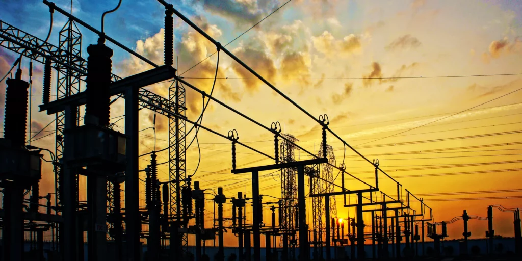
Among the graphical tools for dissolved gas analysis interpretation, the Duval Triangle is among the most widely used worldwide. Developed by Michel Duval at the Hydro-Québec Research Institute [1] and subsequently incorporated into both IEEE C57.104-2019 [2] and IEC 60599:2022 [3], it provides an intuitive, normalised approach to fault type classification that has been validated across a large population of known transformer faults.
Understanding how the Triangle works, what its Pentagon companion adds, where their limitations lie, and how they fit alongside severity-based interpretation methods gives utility engineers a complete picture of modern DGA practice.
Physical Basis: Why These Gases, at These Ratios?
The Duval Triangle uses three gases: methane (CH₄), ethylene (C₂H₄), and acetylene (C₂H₂) [1]. Each gas is produced by decomposition of transformer insulating oil at different temperatures and energy levels, and the relative proportions of these three gases reflect the temperature and energy regime of the causative fault process.
CH₄ (methane) is produced primarily by moderate thermal decomposition of oil, at temperatures approximately 150–300°C. It is the dominant product of low-to-moderate thermal faults.
C₂H₄ (ethylene) dominates at higher thermal decomposition temperatures, approximately 300–700°C. High ethylene relative to methane indicates a high-temperature thermal fault: a hot spot in the winding or core operating significantly above normal temperature.
C₂H₂ (acetylene) requires very high energy for formation, approximately 700°C or above for sustained generation, or lower temperatures for brief intense events such as electrical arcing. Its presence indicates high-energy electrical discharge; even small concentrations are diagnostically significant [1][2].
By plotting the relative percentage of each gas, normalised to 100% total so that the result is independent of transformer oil volume and absolute gas concentrations, the Duval Triangle places any DGA result in a zone corresponding to the temperature range and energy regime that produced it.
The Triangle Zones
The six fault zones in the Duval Triangle [1][2] are:
- PD (Partial Discharge): Dominated by CH₄ with low C₂H₄ and very low C₂H₂. Associated with partial discharge in gas-filled voids in the insulation system.
- D1 (Low-Energy Discharge): Elevated C₂H₂ at low absolute concentrations, indicating low-energy electrical discharge: sparking that has not progressed to sustained arcing.
- D2 (High-Energy Discharge / Arcing): Higher C₂H₂ relative to C₂H₄, indicating sustained high-energy electrical arcing. D2 classification is a serious finding warranting immediate investigation.
- T1 (Thermal, below ~300°C): Dominated by CH₄ with minimal C₂H₂. Low-temperature thermal fault, typically associated with overheating at joints, contacts, or core hotspots below the critical temperature for significant ethylene generation.
- T2 (Thermal, ~300–700°C): Mixed CH₄ and C₂H₄. Moderate-to-high temperature thermal fault: overheated conductors or core at temperatures producing both methane and ethylene.
- T3 (Thermal, above ~700°C): Dominated by C₂H₄. Very high temperature thermal fault. At the boundary between T3 and D2, mixed thermal/electrical mechanisms are possible.
A boundary zone between D1/D2 and T1/T2 (the "DT" zone) reflects cases where both electrical and thermal fault mechanisms may be present simultaneously.
The Duval Pentagon
The Duval Pentagon [4] was developed to address limitations of the Triangle. By adding hydrogen (H₂) and ethane (C₂H₆) to the three gases used by the Triangle, the Pentagon provides additional discrimination between fault types that can produce similar Triangle positions.
The Pentagon is particularly useful for distinguishing partial discharge from low-energy electrical discharge. These faults can produce similar relative proportions of CH₄, C₂H₄, and C₂H₂ but differ in their H₂ and C₂H₆ profiles. The Pentagon also provides better discrimination for certain borderline thermal fault classifications.
Duval and Lamarre [4] demonstrated that using both the Triangle and Pentagon together, with agreement between them increasing diagnostic confidence, provides materially better fault classification accuracy than either tool alone. IEC 60599:2022 [3] includes both methods; IEEE C57.104-2019 [2] incorporates the Triangle and references the Pentagon.
Reading Sequential Results as a Trajectory
One of the most valuable applications of the Duval Triangle is plotting consecutive DGA results from the same transformer on a single diagram. A stable fault will produce points clustering in one zone. A progressing fault will show movement, from T1 toward T2, from D1 toward D2, or from a thermal zone into the DT boundary, that reveals the direction of fault evolution.
This trajectory information is diagnostically important. A transformer moving from T1 toward T2 over successive samples indicates a thermal fault that is intensifying; the appropriate response is different from a transformer with stable T1 readings over the same period. The Triangle provides this trajectory visibility in a graphical form that is immediately interpretable.
What the Triangle Does Not Tell You
The Duval Triangle and Pentagon answer the question: "What type of fault does this gas pattern indicate?" This is valuable information for directing follow-up diagnostic activity: knowing whether to look for a thermal hotspot or an electrical discharge fault guides the subsequent testing and inspection strategy.
However, the graphical fault classification methods do not answer the questions that are most critical for fleet management:
How severe is this fault? Two transformers both classifying as T2 in the Triangle may have very different cumulative fault histories and current rates of gas generation. The Triangle treats both identically.
How urgently does this require action? The Triangle provides no quantitative indication of failure probability or relative fleet risk. A T2 classification does not tell you whether this transformer should be inspected next week or next quarter.
How does this transformer compare to others in the fleet? The Triangle result is specific to one transformer at one point in time; it provides no fleet-relative context.
These questions require population-based severity analysis. Dukarm et al. [5] demonstrated that CSEV (Cumulative Severity) and HF (Hazard Factor), derived from statistical analysis of transformer failure population data, provide the severity and urgency dimensions that fault classification methods cannot supply. In Transformer Oil Analyst™ (TOA), Duval Triangle and Pentagon fault type classifications are displayed alongside R-DGA severity metrics, providing both dimensions in a single analytical view.
Limitations and Applicability Conditions
Low concentration results. The Triangle and Pentagon use relative proportions of gases. When absolute concentrations are very low, near laboratory detection limits, small measurement errors produce large apparent movement in the triangle position. Results with total CH₄ + C₂H₄ + C₂H₂ below approximately 10 ppm should be interpreted cautiously. Dukarm [5] notes that measurement uncertainty is substantial at low concentrations.
Alternative insulating fluids. The Duval Triangle zone boundaries were established for mineral oil. Natural ester and synthetic ester fluids have different gas generation characteristics: they produce different ratios of hydrocarbons at the same fault temperatures [6]. CIGRE TB 771 [6] provides guidance on modified interpretation criteria for ester-filled transformers; applying mineral oil Triangle zones directly to ester transformer data will produce incorrect fault classifications.
Carbon gases. The Triangle does not use CO or CO₂. For thermal faults, the carbon gas profile should always be reviewed alongside the Triangle result: an increasing CO/CO₂ ratio with T2 or T3 classification indicates cellulose insulation involvement, which substantially changes the maintenance urgency and response.
For the technical basis of DGA interpretation methods used in TOA, visit the Science page. For additional educational resources on DGA, visit the Learn page.
References & Further Reading
- [1]Duval, M., “A Review of Faults Detectable by Gas-in-Oil Analysis in Transformers” IEEE Electrical Insulation Magazine, 2002.
- [2]IEEE C57.104-2019, “IEEE Guide for the Interpretation of Gases Generated in Mineral Oil-Immersed Transformers” IEEE, 2019.
- [3]IEC 60599:2022, “Mineral oil-filled electrical equipment in service: Guidance on the interpretation of dissolved and free gases analysis” IEC, 2022.
- [4]Duval, M., Lamarre, L., “The Duval Pentagon: A New Complementary Tool for the Interpretation of Dissolved Gas Analysis in Transformers” IEEE Electrical Insulation Magazine, 2014.
- [5]Dukarm, J.J., Draper, D., Arakelian, V.K., “Improving the Reliability of Dissolved Gas Analysis” IEEE Electrical Insulation Magazine, 2012.
- [6]CIGRE Working Group A2.43, “DGA in Non-Mineral Oils and Load Tap Changers and Improved DGA Diagnosis Criteria” CIGRE Technical Brochure 771, 2019.
Delta-X Research develops Transformer Oil Analyst™ (TOA), the market-leading tool for managing and interpreting insulating fluid test data for high-voltage apparatus. Founded in 1992 and based in Victoria, BC, Canada, the team applies Reliability-based DGA methodology to help utilities worldwide assess transformer health and prioritise fleet maintenance decisions.
Related Articles
Delta-X Research at the IEEE Rural Electric Power Conference 2026
Sean Casey is representing Delta-X Research at the IEEE Rural Electric Power Conference, connecting with rural and municipal utility engineers on how Reliability-based DGA helps smaller utility operations manage transformer health analytics, identify early fault indicators, and prioritise fleet maintenance with limited internal resources.